

Seafarer Mini-Seacourse
I have been asked a few questions about this venerable product,
being the proud owner of one that came from a boat jumble a few years
back and so I thought that I would create a webpage about it. This is
the beginning...
Basically, if you have one and it works, use it . Dont throw it out
until you have tried it.
It will outlast many other more flashy units which get seawater in and
die.
If it nearly works, you should be able to get it fixed fairly cheaply
by the 'radio ham' type of character :-)
Mechanical
The weak point of this product is the plastic end of the actuator.
Intended to break before the rest breaks but no longer replaceable. I
had to get one turned out of brass bar by a friend to replace the one
that was broken off when I bought it.
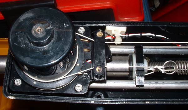
Internally the actuating part is via a nice lead screw attached to a
geared motor . The motor is a really good quality one and it
makes 'robot' noises when it is moving. No belts or channels full
of ball bearings here . The down side is that if it hits the end stop
it tends to jam slightly and you often have to wait for it to unstick,
by adjusting the course knob to encourage it to move the actuator the
other way.
Excess water drains out through holes in the bottom. The electronics
board is clamped to the motor in mid -air so there is less
possibility of water damage. The control knob protects the hole in the
top of the case.
Electrical
These units are basically a textbook example of how to make an
autopilot with the least possible electronic components.
It features overload protection by measuring the motor current .
It ticks if the motor is stalled. Each tick is an attempt to restart
the motor.
All of the electronic components apart from the sensor are still
available and can be replaced with equivalent parts. No microprocessor
here.
The compass unit is a magnetic compass in an alcohol-filled bulb
with a yin and yang shaped shutter that is attached to the needle. The
yin and yang obstruct beams of light from LEDs to photocells.
The idea is that the compass unit is rotated until it points north at
which point the actuator will stop, with yin and yang equally
obstructing the light beam. Turn one way or the other and one of the
light beams gets more obstructed and the other gets less obstructed.
Electronics detects this and decides the direction of movement of the
actuator.
For fans of control systems this is a bang-bang system with a deadzone.
Integral feedback is achieved by turning the compass unit with a bit of
string attached to the shaft driving the actuator as the actuator moves.
The weakness here is the string slips and the electrical contact from
the compass gets dirty.
String can be replaced and the contacts cleaned.
Installation
As far as I can tell the best installation is with the unit level with
the boat at rest and attached at right angles to the tiller, 50 cm from
the pivot point of the tiller on the starboard side.of the boat.
The pin on the base is slightly larger than normal Autohelm - I had to
drill out a socket. The socket will engage with the Autohelm bracket
on the tiller.
Because of the non-gimballed compass do not expect the unit to work
above about 20 degrees of heel. At that point the compass jams and you
start going in circles. The GK24 never really gets too heavy on the
helm when heeled sailing to windward , so overloading the motor is not
an issue. This domain of sailing is really a job for a windvane or a
human.
- The controls are on/off which turns off all the power
- The compass dial control which you twist firmly to point N at
north when the boat is on the desired course with the actuator central.
Because of the feedback, the dial will move as the actuator moves.
Usually several attempts will be needed to get the heading correct. Do
not expect to manage better than 5-10 degrees, as you have to make the
string slip inside the unit to get the compass dial to move. Nylon
string stretches slightly!
- The yaw control. Adjust this changes the dead band, hence the
amount of yaw off course before it is corrected. It needs to be
adjusted to suit the boat and the conditions. If it is set
too small the autopilot 'fidgets' and keeps on moving. Too large and
the boat zigzags along.
Getting inside the box
The bit that went wrong on mine was some dirty electrical contacts
under the compass bit - to get inside pry off the little cap on the top
of the black compass knob and then unscrew the screw. Undo the screws
underneath the unit, remembering which one went where as they are
different lengths.
The works will then be revealed.
If you want to get at the contacts under the compass , you need to note
how the string is fitted around the black compass unit and remove one
spring and detach the string. Undo 4 screws and lift up the compass
unit. Under there are some brass contact wires . If they look tarnished
use brasso or fine emery paper.
Rea-assemble in the reverse order. The long screws are extremely
difficult to line up properly and extremely easy to cross the threads.
Dont force them in .
Afterthought/babble
It would be easy to drive this from a PIC microcontroller and provide
more sophisticated control from e.g an NMEA input. Provide a switch to
disconnect it and then you have the best of both worlds. An autopilot
that fills up with seawater and dies but can steer to GPS and another
that still works.
Inside views of electronics board
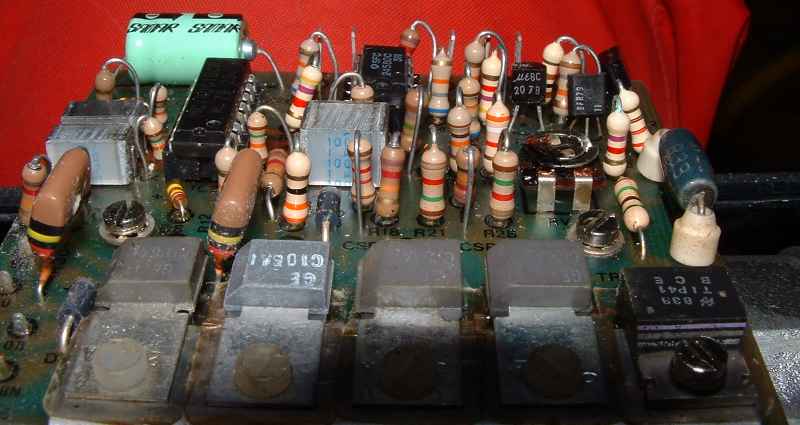
I took this picture on the 28th January when I pressure washed the boat
on the scrubbing piles, and had some spare time. This shows the
controller board. The big resistor is 0.33 ohms.
The idea is that the C106A thyristors are arranged in a bridge
arrangement with the TIP41 acting as an on/off switch.
To turn the motor , the TIP41 is turned on and two of the four
thyristors are triggered. They remain on until the TIP41 turns off,
either because the autopilot wants to or the voltage across the 0.33
ohm resistor becomes sufficient to turn on one of the other
transistors, because the motor is stalled.
About 2 amps would seem to be right. If that happens the TIP41 is
turned off for a while. A bit later on it is turned on again, and off
immeidately if there is an overload still present (the voltage across
the resistor is still large enough due to the current). If the overload
has gone then the motor will draw less than 2 amps (or does RV1 set the
current limit to something higher) and so the autopilot continues to
work. If you completely short the motor the protection is probably not
fast enough to prevent things blowing up.
Equivalent parts : I checked Cricklewood Electronics website via Google
and they either have the parts in stock or still list them on the
catalogue
MC14001= CMOS 4001
SFC2458=MC1458 op-amps
TIP41=BD243
BC207=BC547
BFR79=BC557 : different pin out : need to refer to datasheet.
C106A= thyristor with a sensitive gate pin : any 50V 5A device I
suppose
According to the date codes on the devices here it was built using
parts made between 1979 and 1983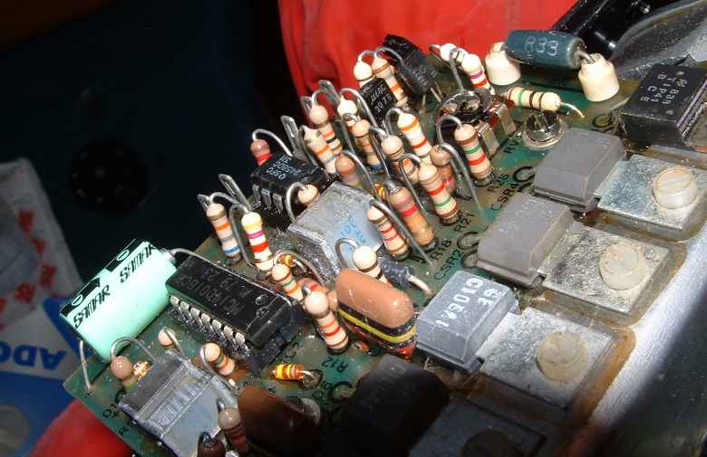
String Layout
I have been asked a couple of times to provide detail of the string
layout inside the unit as there is a great tendency for 'someone' to
have a fiddle and mess it up.
Compass End
Here we can see the ram at near full extension. The string is attached
to the end of the spring which is nearly fully extended (this is
actually a bit tight). It then wraps clockwise around the compass unit
for 1.5 turns and then goes to the little gearing wheel at the other
end of the
unit.
Motor end
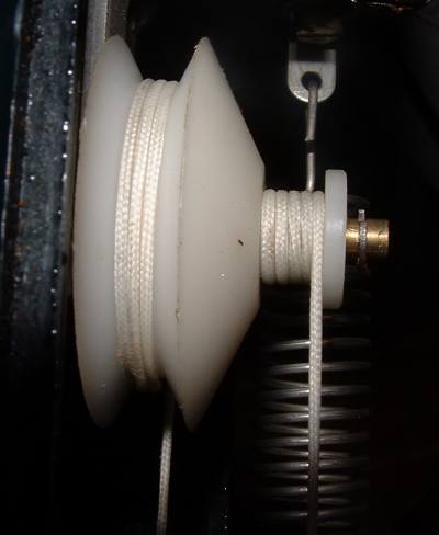
What is critical here is that at this point there is still at least a
couple of turns of string on the larger bottom spool of the gearing
wheel (it reduces the movement of the ram to a smaller movement of the
compass)
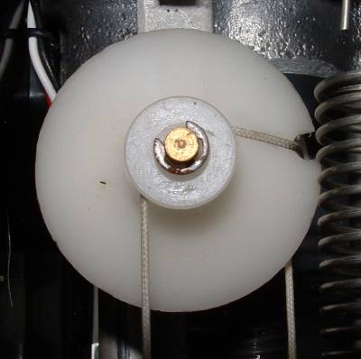
This is the same thing from the top. String to left goes round compass.
String to right goes to the end of the ram.
More Documentation
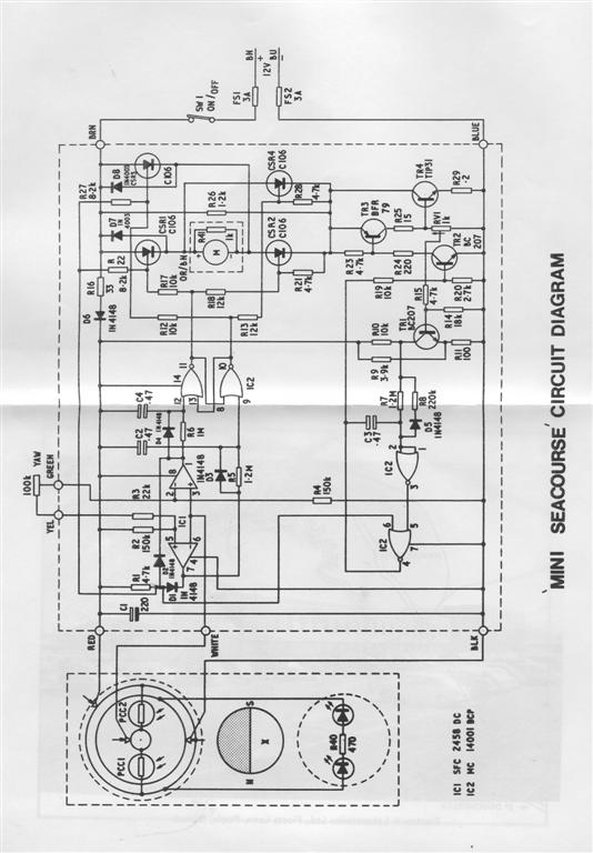
I have subsequently recieved some more JPEG files giving the circuit schematic and the theory of operation
I include these here
.jpg)
.jpg)
Page © Mike James 13th April 2008
Comments to:
mike@hamble.demon.co.uk