Link back to Radio Zone

Repairing the HP141T with 8554B Spectrum Analyser


What is it ?

This is a spectrum analyser built into a 1970's technology analogue storage tube oscilloscope chassis.
In the plugin bay is an IF and video unit (the lower half of the panel) and an RF unit in the upper half of the bay.

The RF unit provides an IF and outputs are provided for the first and third Local Oscillator (the second LO is fixed ) for an associated 'tracking generator' 8443/4 which is essentially a mixer and filter block. Aligning the 8443/4 frequency is performed by tuning the second Local Oscillator in the 8443/4 unit.

The IF unit implements all possible resolution bandwidths (downto 10Hz ) but the selection is controlled by a switch on the RF unit as the higher frequency RF units have less stable oscillators so the Res. BW is limited to 100Hz for the 0-1250 MHz and 18Ghz  units by the wiring of the switch.

Different RF units can be mated with the IF unit  by removing both from the chassis, then sliding a latch behind the front panel.

There are  several basic RF units and a lower spec economy  IF unit  8552B and high spec IF unit 8552A .

HP8556
20Hz to 300kHz
Audio
HP8553
1kHz to 110MHz
RF tracking gen HP8443
HP8554
100kHz to 1250MHz
RF tracking gen HP8444
HP8555A
10Mhz to 18GHz
Input RF is mixed down  with a harmonic generator in the RF unit into the 0-1GHz range (basically an 8554 with a harmonic spike generator and mixer).
Needs HP8445 preselector  'in dense environments'

The tubes in the storage scope can be poisoned by epoxy resin vapours released from parts of the construction of the tube, specifically the bonding of the face plate. A limited supply of these tubes appear from time to time on eBay
For a website with information about how to interface the HP141T to a PC , go to : http://f1frv.free.fr


My repair story


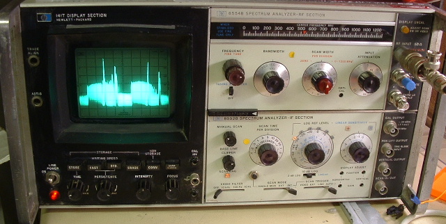
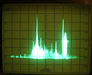
A picture of it working
End Result
What I started with
In the beginning
What it was like
First Impressions
The first fault
No_tuning
The most obvious problem Burnt_resistors_in_the_power_supply_
Locating service manuals on US Army website
US_Army_to_the_rescue
Choosing new resistors
Resistor_Replacement
Another fault on the timebase unit
Almost_Short_Circuit
Mistake
More_smoke
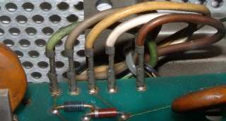
Finally spotted another mistake
Similar_coloured_wires_again
Fatal flaw exposure after...
I_did_up_all_the_screws...
The last fault
Holdoff_timing_leakage
Conclusion
Working_still
Some time later. Continued problems fixed and outstanding
In_use
More In use Jan 2007 More In Use


The end result firstPicture of working analyser

This picture shows two DTV transmissions (low noise-like signals with a flat rectangular spectrum) each adjacent to analogue PAL transmissions (largest spikes being carrier and sound 6MHz above) with mono sound and NICAM stereo being picked up on a 2m amateur band J-pole in the loft of the workshop/garage. The terminators on the LO outputs are from old Ethernet cabling.


In the beginning

In late 2002, a friend of mine offered me a couple of bits of  non-functional RF test gear on a 'take it or it goes in the skip' basis. As I had just created a garage electronics workbench, I jumped at the chance to  take it, especially as they turned out  to be  a  spectrum analyser (the HP141T) and a communications test set (Stabilock 4040).
The 4040 seemed to be mostly working but on closer investigation it has some fault in its synthesiser(s), and it came with a rudimentary block diagram in its manual. I am still working on it, slowly around boat maintenance and sailing.
The main focus for me  was on the HP141T. It was the 8554 version covering up to 1250MHz. On arrival it had one manual for the 8554 RF section.

First impressions

Apart from it being very heavy and a bit dirty, the instrument looked in a reasonable condition: the selector switches on the bottom row had got a bit bent and one had lost its little triangular handle.  Some wire insulation was pushed over the end of the lever.   
The mains socket was a pretty horrible pre-IEC style 3 pin connector feeding into a  mains filter. For the purpose of testing I soldered a mains lead to the pins of the filter and insulated the live pins. Powering up the HP141T I was greeted  by a loud fan noise, and some lights on the front panel.
On the storage CRT there was a shrunken but normal brightness trace, which could be focussed and adjusted.

No tuning

I connected a wire antenna to the N-type input and then I found that the Zero Span  and the Per Division setting did not seem  to be tuneable, and were stuck around 0Hz.
The 0-1250Mhz setting produced a spectrum, but the marker 'V' was also jammed around 0Hz.  This turned out to be the ten turn tuning pot  which was open circuit. A replacement was bought from Farnell. It is pushed quite hard as it has about 30 volts across a 5k Ohm pot. A bit of  fiddling with string, screws , grubscrews and Allen keys and the analyser could be tuned.

Burnt resistors in the power supply

Now to sort out the shrunken display. I turned over the instrument and found lots of  high tolerance resistors in the power supply which had been cooked so hard I could not read their values. I noted that somebody had replaced a resistor in one corner of the board with a pair of series 15k resistors.
I tried to decode the shades of brown around the board  to work out the resistor values. I was poking around trying to parallel up extra resistors to reduce the value to something like the marked value when there was a loud bang and a resistor exploded. I think I had slipped with a test probe. I could not read the pieces of shrapnel to work out its value. So I parked the wreck in the corner and left it.

US Army to the rescue

Somewhere along the line came the relaxation of U.S. export control on 128 bit encryption technology, and Ebay.  Occasionally I would Google search on keywords looking for terms related to Spectrum Analysers and I would come up with secondhand prices but not much else.
Along with that on Ebay I would often find a CDROM of old manuals including the HP141T offered as a way of saving on the hassle of downloading from the US army website of manuals.

The US Army URL was given. Fortunately the only thing I needed to access the site was a modern 128 bit capable browser, and time to try lots of search terms on the document titles before getting a list of Hewlett Packard  service and maintenance manuals.  That website is now closed off to non-military people. I can see why as some things with 141 in their serial numbers appear to be capable of damaging people, machines or buildings big-time, things I did not want to see or know.

It was obvious that the HP141T was once  standard US Army issue, as there were a lot of relevant manuals on the site.

I downloaded those relevant to the HP141T and printed out the PDF files (about 250 pages) on my inkjet printer and zoomed the relevant circuit diagrams from the scanned images up to a readable size as separate sheets of  paper. Some of the manual pages begin life as about A3 size, and Acrobat Readers 'rotate and scale pages' option leads to microscopic schematics. Still some are visible.
Without the access to manuals via the internet it would have cost me more money and time to purchase all of the manuals as paper copies on Ebay or from distributors. I am grateful. .

Resistor Replacement

From the schematics  it became clear that the power supply's  burnt resistors were actually meant to be of totally different values to their apparent colour codes. There are  basically 33k, 27k , 22k, 100k and 49.9k resistors which had all gone high or open circuit, in the feedback circuits of each regulator.
The power supply is definitely dangerous being able to output 250 volts at 100mA.
Fortunately Farnell sell 0.75 watt  1% resistors but strangely only in E12 values, meaning the 49.9k had to be made from a pair of 100k resistors.
Is continued availability of widely spaced but accurate power resistor values due to the influence of the valve audio renaissance ?
No resistor actually has a dissipation of more than 0.5 watts, but I am sure the new resistors will also succumb to burning out in time. Basically by the end of the game all brownish resistors had to be replaced.
The resistor that was made up from two 15k resistors turns out to be 49.9k or 50k ohms in reality. It didnt help before I had the manuals that the PSU had been modified in the wrong way.
As I replaced the resistors I found that one of the series pass transistors had failed. As it was a 2N3055 I was able to find one in the junk box and replace it, with one even older  than the analyser with a 1967 date code. The analyser's semiconductors  seem to be date coded  in late-ish 1980.
While testing the power supply it became clear that the resistors needed to be 1% types as the voltages could not be correctly adjusted until the resistors were within 1%. The other (248V , -100V and -12.6V) supplies are all referred to the +100volt output so this has to be setup first.
The power supply can obviously be used to run valve plugins as well as the modern IC based plugins (well it was modern in the mid 1970s to 1980s)
When replacing the resistors, I had to lift up the power supply PCB to get at the underside of the board. To do this I took some digital photographs and then taped together all of the wires plugged onto one side of the PCB. I then lifted them off and hinged the board down. More on this later.

(Almost) Short  Circuit in timebase/IF module

After I had the power supply back to normal a spot appeared on the CRT, as the EHT is derived from an oscillator running off -12.6 volts,  but there was no intensity control. It was in fact at full brightness. More worrying was that the spot stayed still on the CRT but could be pushed off the faceplate by using the manual scan mode and the manual scan pot. I also defocussed the spot to make sure it would burn the CRT more slowly.
The two fuses on the back of the plugin section of the analyser had blown, so I replaced them. The spot had moved but only twitched as I adjusted timebase controls. 
I did not have the full HP adaptor kit with card extenders and cables but I was able to access the test points on the plug in modules in the timebase with all of the screening covers off. It was clear that the +20 volt power supply was only about +3 volts. I immediately suspected the regulator circuit but there was nothing wrong with any of the semiconductors.
I noticed that the 20V regulator's dropper resistor (big golden wirewound on the back panel) was dropping from 100V to something like 9V (should have been more than 20V to give the regulator transistor a chance).
There was probably an overload in the power supply, and indeed on checking there was only a few ohms resistance between +20V and ground when the power was off.
So I started unplugging PCBs and re-powering the instrument. It was then clear that the short was on the deflection amplifier board. There was only one possible DC path through to earth which could be less than a few ohms, the supply decoupling capacitor. A 20Volt working 15uF capacitor was not working at 20V any more. I removed it and the instrument started doing things.
No blanking and no brightness control.

More smoke

I looked back in the power supply and began to suspect crossed wires where I had removed and  replaced them. There were a pair of similarly striped and dirty wires connected as a pair some distance from their neighbours , looking like I could have put back in the wrong places, which I swapped. One of these was the fast blanking wire.
The deflection board smoked and the trace vanished. I put the wires back and dug back into the deflection board , where I found one resistor and one video transistor in the Y amplifier gone. These were replaced with spares from my oscilloscope repair kit but still no Y deflection. There were some op-amps on the board. I tried replacing the Y deflection op-amp with an LF357 which I had lying about and I was greeted with a trace that could be adjusted and which meant something.
Still no blanking and no intensity control.

Similar coloured wires  again

I looked back on the power supply board and realised from the schematic that it was possible that the grid and cathode connections to the tube had been swapped. There was a greenish-grey wire to the cathode and a greyish-green wire to the grid. Looking at the digital camera photos more carefully, I could see the transposition of the wires. Note how the greenish wire is pulled tighter in the original pre-mistake image. I claim that the poor light (the analyser obscured the workbench light)  and the  room temperature of about 5 Celsius slowed my brain.
wires
The right way around and then the intensity could be controlled. Still no blanking.  In the end I started checking semiconductors around the blanking circuit and eventually found there were 2 diodes open circuit in the fast blanking line, and the snubber diode on the reed relay in the slow blanking circuit (for storage use) was short circuit.
Replacing these with generic silicon diodes from the junk box and the trace could be blanked.

I did up all the screws...

And started playing. At first all was normal until I tried to look at the close-in spectrum of a band 2 FM transmission. And the timebase stopped or rather started twitching with the sweep light just blinking, as it went from 200mS/div  to 500mS/div. I was sure it was working 2 years ago...
So out with the timebase board and an explore of the timebase switch. A red herring was not reading the carefully described schematics for the wafer switch, and somehow rotating the schematic relative to the switch.

Holdoff timing leakage

Eventually I traced the problem to a holdoff timing circuit which seemed to be re-triggering itself. There was a 3.3M resistor which charges up a capacitor on the timebase switch which had become 3.8M and it looked like a nasty carbon resistor. It was shorted out by the switch at faster timebase speeds than the problem speeds, and in circuit for all of the bad timebase speeds.
I replaced it with a 2.7M resistor from the junk box and for a while I had slow timebase speeds operational until the analyser warmed up from 5 Celsius. Even then the single sweep button did not seem to work properly - each press starts or stops the scan in turn.
None of the transistors feeding the circuit were actually faulty and they all had good gain of about 170 according to the £2.50 Chinese multimeter from Maplins. All the same I replaced two transistors connected to the timing circuit  with other PNP transistors (2N4126 which are TO92 reversed pinout) which have basically the same gain. The cure was replacing an emitter follower that must have had some leakage or lower gain in reality (probably due to spikes on the power rails when I was poking around), and which was counteracting the 3M resistors that discharged the holdoff timing capacitor.

Working still

The last time I turned it on it was still working. Another PAL TV spectrum ....
PAL TV transmitter
Image shows vestigial lower sideband, sound subcarrier at 6MHz above (calibration sort of OK!) and NICAM728 audio at about 6.5MHz above carrier.  Baseline clipper used to eliminate bloom from noise. 

Interestingly there are unused IF filter bandwidths down to 10Hz inside the IF for use with lower frequency RF units which have less residual FM in the local oscillators. The IF bandwidth selector switch is therefore on the RF unit  with inappropriate selections disabled.

 It is strange not having a microprocessor in the box and having to think hard about transferring calibration from the 30MHz -30dBm calibration source to the settings of the analyser. On the other hand it doesnt sit there twitching its display like an a Marconi analyser which we once had at work. It kept on recalibrating between sweeps across the band . It spent a lot of time back at Marconi and kept on coming back with new revision numbers and the same fault.

I think that the total cost of  components to repair the analyser is about  £30 and  it has taken probably  several weeks worth of  evenings over 2 years.


In use (April 19th 2004)

Non-linear scan timebase

I noticed that the scan speed was not really controlled by the timebase switch, changing every 3 positions as the capacitors were switched. It was also obvious that the scan ramp was not linear but more exponential in shape. I found that the timebase current source transistor (PNP) Q6 only had a gain of 6 so I replaced it with another  PNP transistor, and then the timebase came under control properly.

Trigger failure and slow timebase failure

I then also noticed that triggered timebase mode was only available for the fastest set of 6 speeds, and the incomplete scanning came back for the slowest 6 timebase speeds, from 0.2 to 10 sec/div.
This turns out to be the effect of the power supplies needing adjustment after the plugins are replaced for the HP141T mainframe when used as a spectrum analyser. When used as a scope the setup procedure can be done off  load. With the spectrum analyser plugins plugged in the -12.6 volt rail reached -11.2 volts. Erratic triggering performance was entirely due to this.

Flickering Persistence and Storage display fault

Something in the flood gun circuit is noisy so the persistence is extremely variable even if one does not touch the pot. In store mode one cannot see a trace except in minimum store mode . This fault is still outstanding.

It died again, blew some fuses and annoyed me until I realised that a track had fallen off the PCB in the power supply as I have done so much poking , soldering and re-soldering !

Further to this it turns out that more resistors needed replacing in the PSU as the +100volt rail voltage is critical to the correct operation of the storage persistence flood guns.

Still no longterm storage. Do I really need it ?


More In Use (January 2007)


I had finally repaired my Stabilock 4040 and then I connected it to the HP141T. It seemed to be producing the right level at 900MHz but showed a rolloff at low frequency. I repaired the broken centre core connection on the coax interconnect.  Nice flat output level from the generator displayed by the analyser. But there was a problem.

32KHz sidebands on the plot

At 50dB down from the carrier, offset by 32KHz and harmonics there were sidebands on the output of the Stabilock 4040. So I tried a 2 metre rig through the useful 20dB built-in 50 watt capable power attenuator on the Stabilock 4040. This too had the sidebands. I therefore assumed it was the HP141T . Strangely the EHT generator in the HP141T display runs at about 32KHz. So I looked at the HT rails and they were noisy and not well regulated. In fact the +248 rail was at +217 volts, the -100 volt rail stuck  at -81 volts and the voltage adjustments were not working. I dont think I have ever had the voltages right.

Debugging the power supply

I unplugged the scan and RF units and poked around the power supply.
I began by getting the -100 volt rail to the right voltage. This needed resistor values to be altered from the PCB design (which seemed to be correct if you did all the calculations). Basically there is a longtailed pair which was designed to run with 20 volts across the transistors but needed this to be wound up to 30 volts to get the regulator to power up and begin regulating. Perhaps thats why the resistor values seemed 'strange' when I started working on the HP141T all those years ago.
I then found one short circuit transistor  in the +248 volt regulator. So I replaced it with a PNP polarity device . Previously someone had put in an NPN transistor in this position.
The scans in the service manual are too small and you cannot tell the NPN from the PNP devices apart on the schematic by their symbols.
The clue is in the fact that there are protection diodes across the base-emitter junctions protecting them against reverse bias.
Still the power supply would not regulate. Somewhere down the line I got +303 volts from it, and then  +217 volts again. I checked all of the voltages in the circuit without any transistors present  and they were right apart from the first potential divider feeding back from the +248 rail. Voltages here were almost but not quite right.  After a lot of disbelief I tried the resistor values . A 100k resistor which I had already replaced with 200 volts across it was open circuit, and a parallel pair of 100k resistors (to make 49.9k) with  150 volts nominal across it had increased equally in value to 130k ohms. Something strange here. I wonder if its a flashover in the CRT which somehow pushes the +248 rail high and damages these modern resistors. So I replaced the resistors with the last of my replacements and finally got  -100,-12.6 , +100 and +248 volts on load.

I put in the scan and RF units and then something went bang in the output driver PCB. Another of the silver ITT electrolytics had blown, a 35 volt working cap with 20 volts nominal across it. A hole was melted in the side of the capacitor and some smoke had fired out. Easy to find and replace with a component removed from a PC power supply. Ran out of 1 amp fuses so off to Maplins for another packet. Replaced fuses.

All seemed well apart from having a minor panic over flatlining on the CRT caused by having selected 10Hz video bandwidth and 100us/div scan rate on full scan width mode. All  that works then is the notch marker for the centre frequency position.
Switches in the right place, a quick tweak of the X gain and offset controls and back in business.

Success

And the 32kHz sidebands have gone down as well. The display flickering went away. Perhaps its because the PSU board relies on 5 out of 6 of its mounting pillars as earth returns.


And then it went blank again

I turned the unit back horizontal after putting the covers on. The trace was flickering again. Then the lights all went off on the front panel. It had blown the +100 volt fuse. So I checked and there was indeed a short circuit which kept on going away as I unplugged the seven wires carrying the +100 volts away from the PSU.
Eventually I took the top cover off and found a hairy wire where the movement of a "floating" socket that connected power to the plugin bay had fatigued off the +100 volt wire. It had hit an earthed connection and also had hit the trace blanking signal. Pulling wires off in the wiring loom had dislodged the short.
Re-soldered the wire and then I was getting a trace with no blanking when I replaced the fuse for the fourth time.

In the middle of all this I tripped the mains earth leakage trip. This time I was definitely poking around a tagstrip that floats around trapped by one of the case screws when the cover is on. The tagstrip carried a dropper resistor for the mains power on neon. A bodge by HP which I triggered by poking at it. I covered the chassis beside the tagstrip with insulating tape which is also trapped by the cover so it is less likely to fall off.  So now I know why it trips the earth leakage breaker.

Looked at the deflection driver board and found the blanking driver transistor was blown. So I replaced it but the blanking signal just sat at +20 volts with a very small wiggle representing the blanking signal. It was clamped by a diode directly to the +20 rail voltage. The clamp is intended to limit the blanking signal lower voltage to 20 volts.
 I then checked all the other transistors on the deflection driver board and they were all right. Then I thought I would check the resistors in the blanking circuit: I found a 330 ohm resistor which I had replaced some time back had gone open circuit. It connected the +100 volt rail  to the blanking output transistor. I suppose with all the excitement on the 100volt rail the resistor had suffered from overheating and died. Interestingly it was adjacent to the electrolytic which went bang when I started the latest round of repairs in December.

Somewhere in all this I added to the panic by knocking the dB switch to 2dB/div range which meant the trace was jammed either at the top or the bottom of the screen. I almost started searching for the fault before I tried the user reset  which involves setting most dials and switches to sensible values.

Keeping it going September 2009

When I turned it on the slow scan speeds failed to operate and from memory this was because of low power supply voltage on the -12.6 volt rail. As this was referenced to the +100 volt rail in the crazy plan of the HP power supply, I looked there first. And it had drifted. It turned out that the high voltages had destroyed the 'new' metal film resistors again. So as I had used up all of the resistors of exactly the correct values, they were replaced with series combinations of other film resistors I bought at the same time as the original repair. I hope the lower voltage across each resistor will give a longer life span.

In the end I had to replace about 5 resistors again . This time I also decided to check out the storage circuits as they had never worked 100% and again I found a 301k resistor being used as a collector load , with 250 volts across it. It had gone open circuit, so I replaced it with a pair of 150 k resistors in series. Now the storage circuits drove the tube properly.

I took off the side panel to get at some variable resistors and disturbed an ancient flex strip carrying apparently several thousand volts. It started flashing over - I think this one is the one responsible for air leaks into the CRT as well. So I glued it back together with epoxy glue and it stopped flashing.


Mike James  3rd October 2009